
It’s that time again! Time for another project? Not quite.
Its that time when cash is short because payday hasn’t quite arrived yet, and when it does, I have people to feed and shoes to repair. And yet I stand surrounded by trash, parts, underused tools, and worst of all:
Unfinished Projects
And as the cyberdeck community survey revealed, this is the darkest fear that looms in the minds of deckers and hobbyist electronic-tionados planet-wide. So to allay my filthy, troubled conscience, and maybe clean the place up a bit, I will grab a project based on trash and half-baked projects by the horns: I believe another Geiger-counter is in order.
Seeing as it needs some back story, we need the right name for it. And I quite like the sound of the British military research project rainbow codes.
Something visually matching.
Something aggressive.
Something…

Nailed it. That sounds pretty rad – a mix of opaque secret project coding, with a hint of cold-war nuclear death. This is important, as devices that can measure ionizing radiation is a burdensome signature I have chosen. In other words, as far as budget allows, I want to include a working Geiger-counter in every project I build from now on.
So, what parts are on the menu?
Parts List
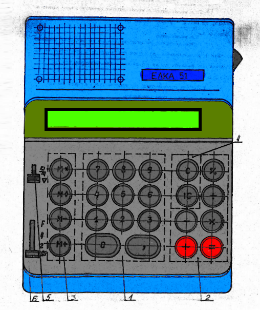
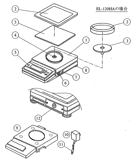
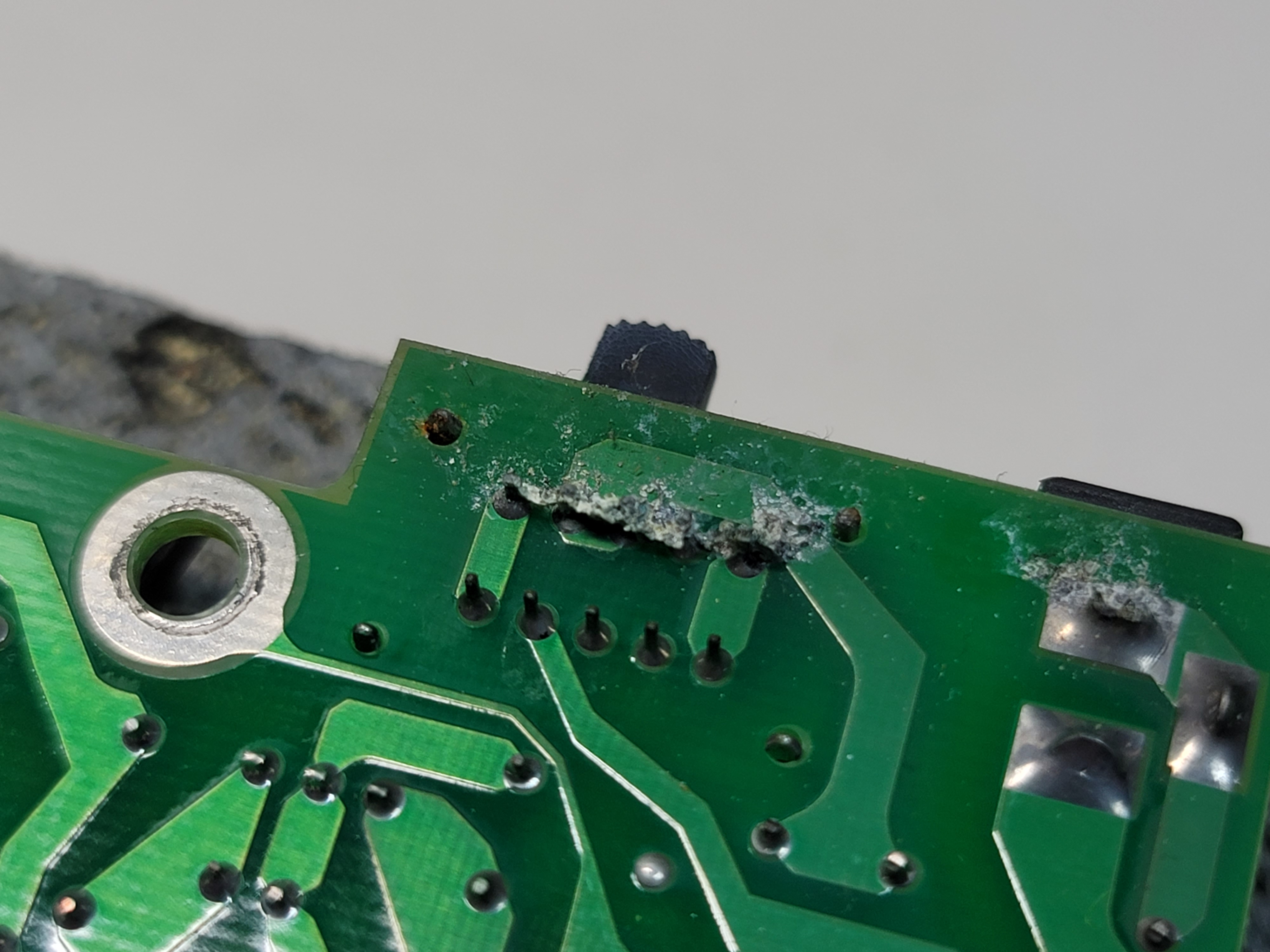
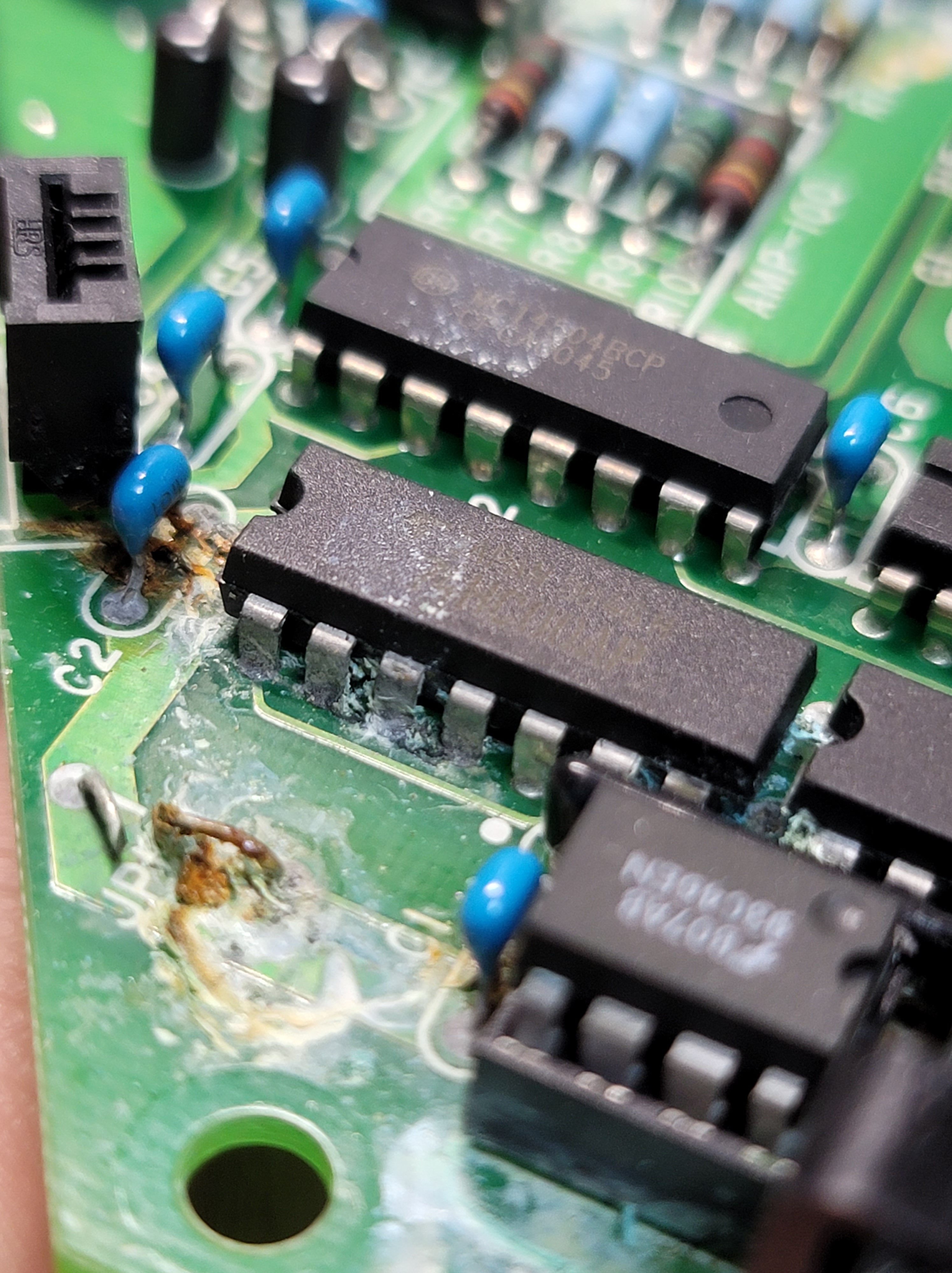
1x badly corroded Shimadzu el-120HA Electronic Scale (encrusted with dirt, animal fat, beige UV burns, and general grubbiness)


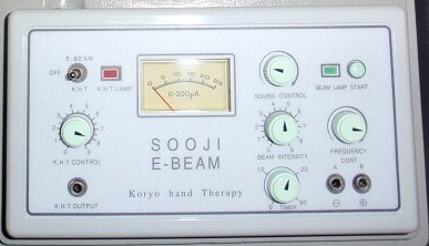
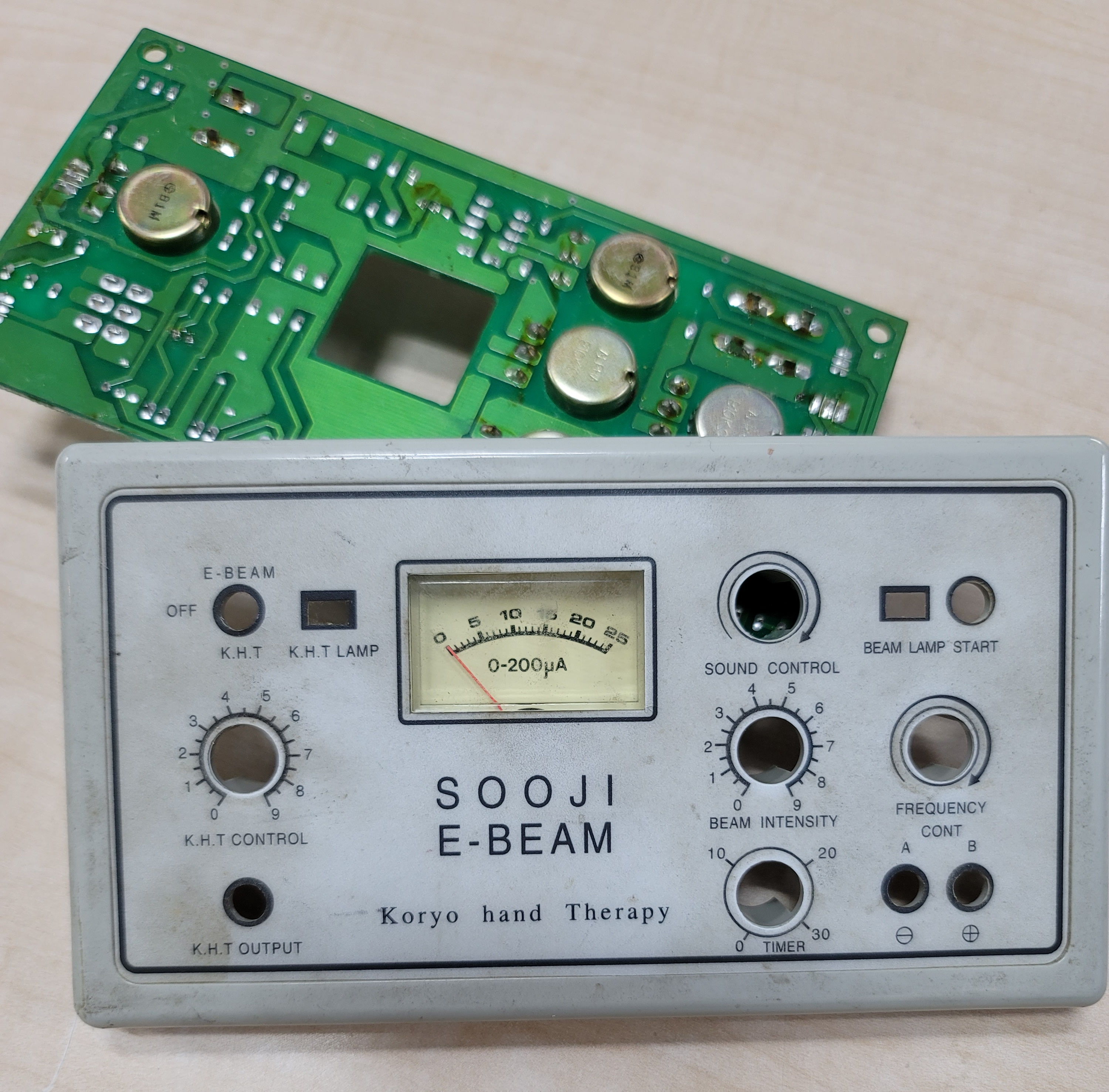
1x abandoned Sooji E-Beam finger acupuncture…thingy (explanation here in a very sketchyville research paper: its made of paper, and some research was done – but good luck trying to figure out what it actually means)


4x potentiometers
1x toggle switch
1x red i2c LCD
1x DC barrel jack
1x fat slider power switch
1x 12mm round non-latching switch
1x SPI ST7789 240×240 Color LCD
1x micro Arduino MEGA
1x SBM-20 400V Soviet Geiger Tube
1x hand-rolled 400V power supply and Geiger interface
1x 18650 single-cell USB to 9V UPS board
Parts Choice: Design Thoughts
Keeping in mind that this all is based on what I have around, and what I can build, the design choice has very little consideration, except to unload my parts bin and achieve maximum coolness factor, while making a tool I can actually use – in other words, if you follow my path and try build something similar, I’m sure you too will not build something exactly the same, but improvise as much as you can, while being resourceful with those dusty unused parts.
As for the choice of the MEGA, I roughly counted the likely number of pins I would need, and found an UNO lacking. At this early stage, I estimate at least 23 GPIO pins needed. (spoiler – I needed much less in the end).
I chose to add two displays, one red I2C LCD, and one small 240×240 colour SPI colour display, and this was because there was already a space convenient for the LCD, but for the colour LCD, there was a space suggestive of being suitable for it. The red and black LCD has a certain style and feel to it that can’t really change, so I will need to design a interface on the colour screen that matches the style.
These red LCDs looks really cool and retro, and I doubt that most people (even experienced makers) are really that familiar with them. They are increasingly hard to find though, so I try use them when I can.
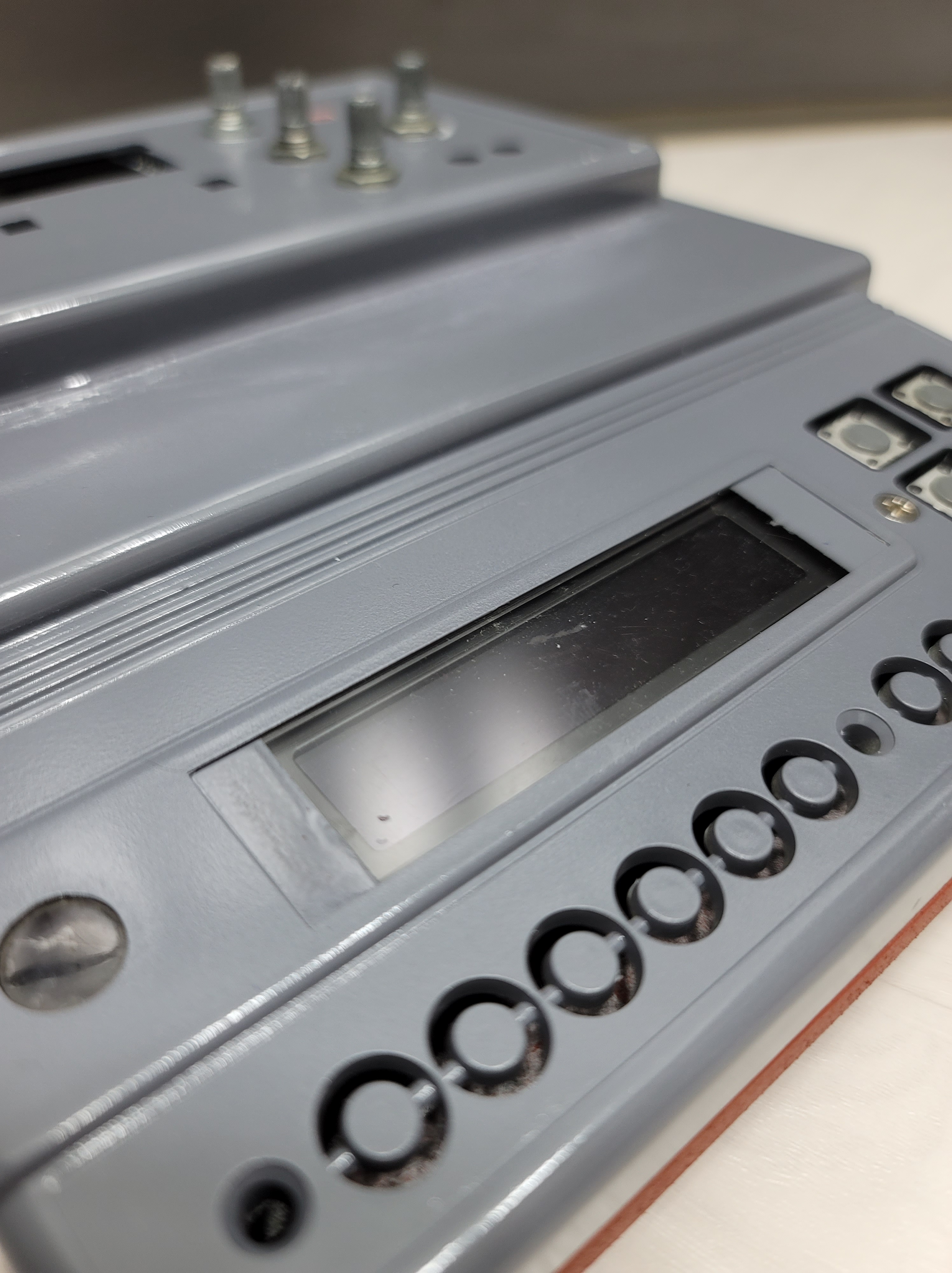
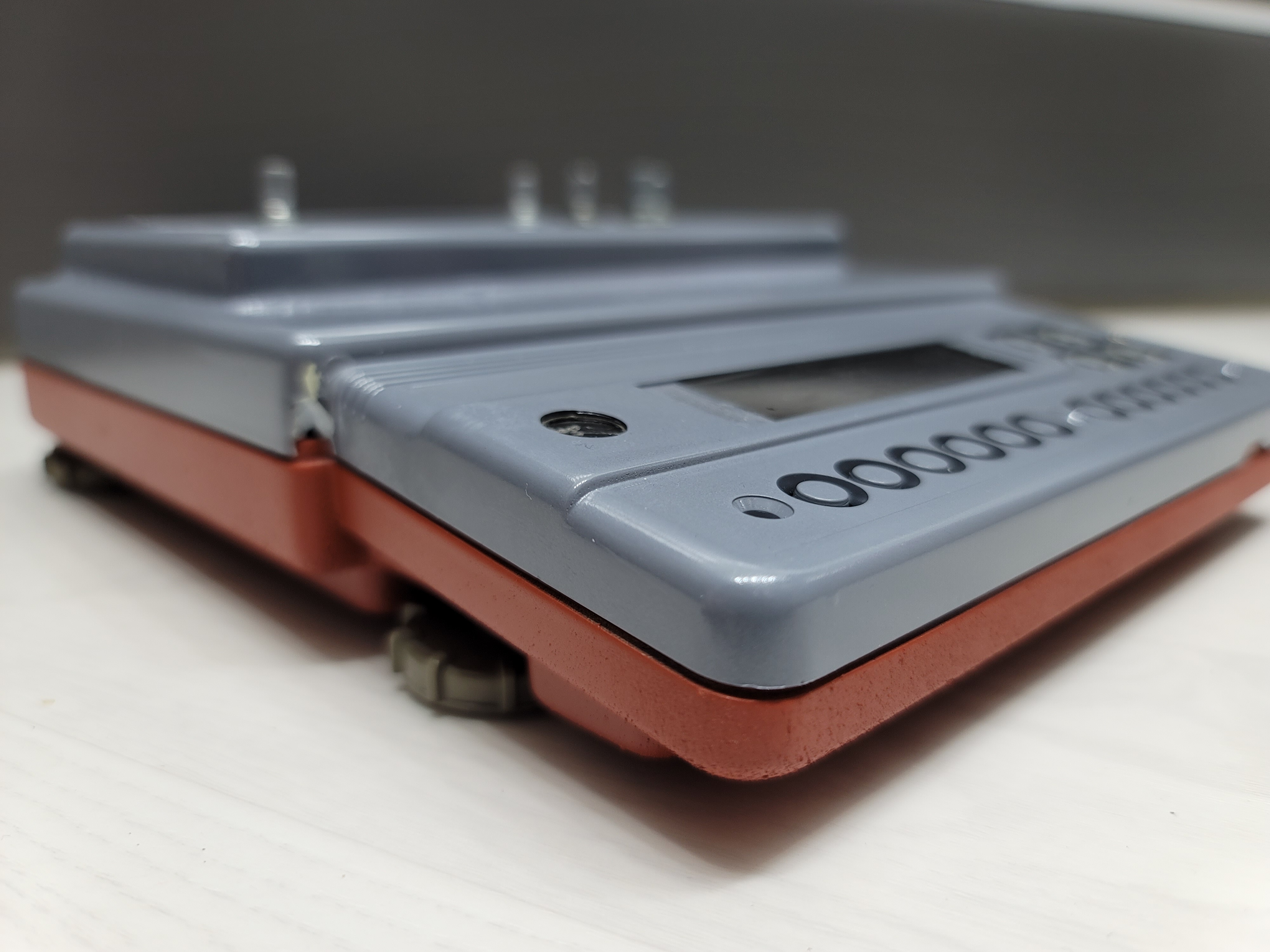
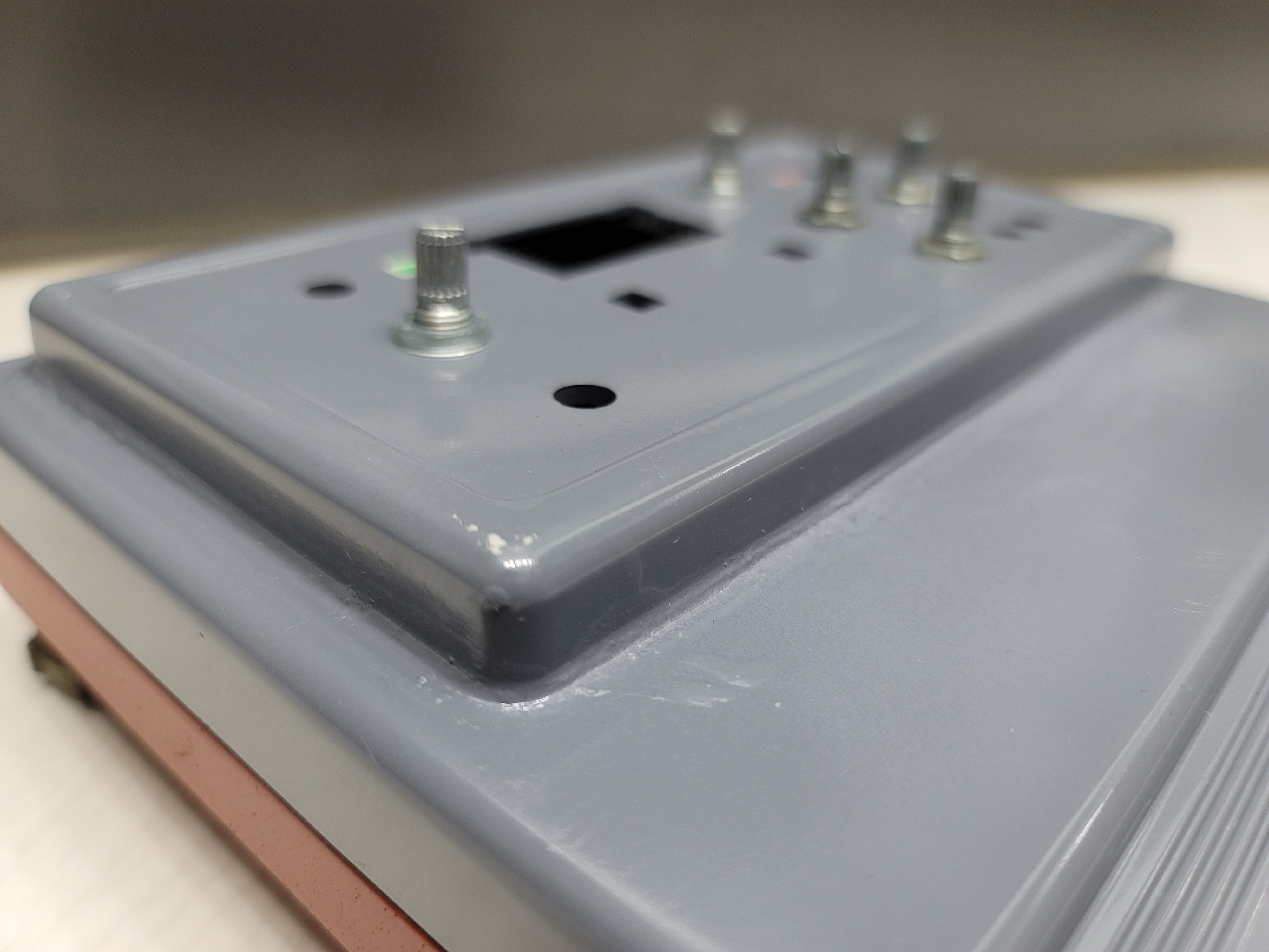
Frankestein’s Casing
The Sooji E-beam thing and the scale both provide two unique plastic and metal molded enclosures, which I combined. This required the use of my new Chinese Bone-cutter Dremel of Doom, as ferocious beast that until now I have been rather wary of. But once I got started, its a fun thing to use (I will still treat it with deep respect and fear…and keep the name Chinese Bone-cutter Dremel of Doom). Then, with plenty of epoxy glue, I pasted them together.
After the glue dried, and several more strategic layers were added, not to mention a bit extra on weak points to strengthen likely break points, I sprayed the top medium-gray, and the bottom a congealed-blood red.
I got so excited that I started populating components, without taking intermediate photos or video. My lack of self-control will doom me to be surrounded by cool projects with absolutely no documentation, and so I will never be a YouTube star. I will die unknown.
Oh well.
The inside of the case is not very spacious, but it has possibility. The scale’s load cell and resistor bridge was housed deep inside within a metal-walled part of the casing, probably for physical stability.
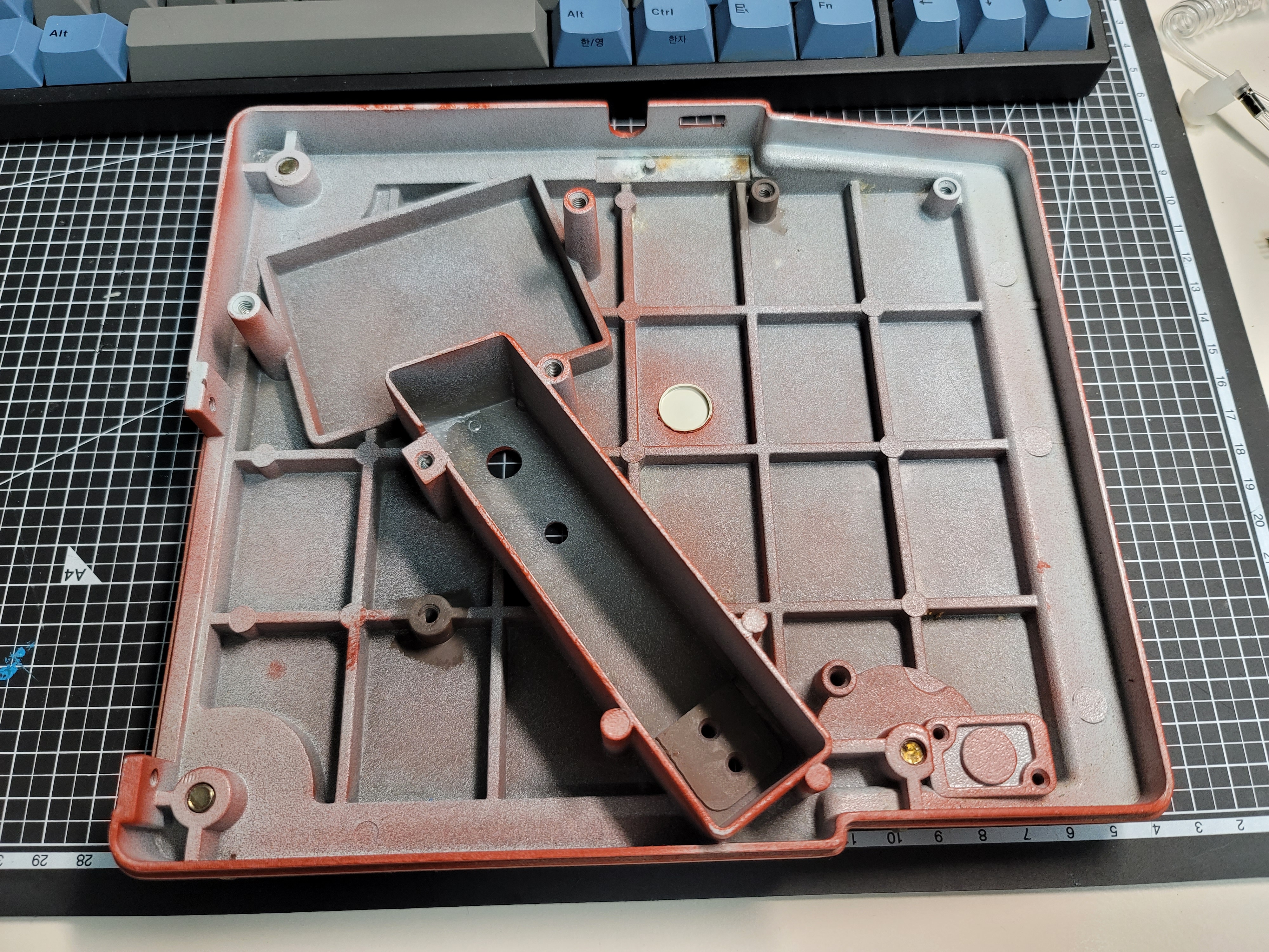


Test fitting shows its all very tight, and its hard to correctly tell what fits and what doesn’t fit. The biggest fear I have is popping the Geiger tube when closing the device, so I’m mulling the possibility of making life simpler and safer, putting the tube outside with its own handheld casing. More work though, because now I need an extra external space, with the right wiring.
Soldering it all together and trying not to break anything will be the next task, and I will likely procrastinate, because it will be a lot of work. We aren’t halfway yet….
[Stardate: 2022-02-04] Build Update:
I made this article and left it sitting for so long, while the story of the counter actually went extremely far, and the TLDR is that I have a stunning, perfectly working Geiger-counter, a one-of-a-kind. But this is a long story.
Stay tuned for Part Two.
Paul Hoets is a freelance maker who lives in South Korea. If you liked this article and would like to contribute to his empire of dirt, silicon and tech. education, buy him a coffee!