Note: this example is specifically for Arduino Uno//Leonardo//Pro-micro.
i2c is a protocol used for certain OLED displays, LCDs, many new and cheap sensors, and even if you want one microcontroller to talk with another. This guide shows how you can connect the i2c device to an Arduino-type microcontroller, and poll its address. These sensors and displays can be used on Raspberry Pi also (as long as they are good for running at for 3.3V).
Sniffing around for i2c on Raspberry Pi is a bit different, and is for another guide, but the basic principle is the same. You’ll use the following code with an Arduino UNO or such to use as a tool to read the address of the connected sensor at 5V, as most sensors designed for Arduino run at 5V. In the case of Raspberry Pi, you’ll be using a 3.3V system. Some hacks to get 5V devices working in 3.3V systems, and visa-versa, are possible, but again: another guide.
The common point is that you need to see if the device is responding to a poll for its address – this proves its alive, and you can use the address to get your code running for that sensor//display.
If you’re working on i2c devices to any extent, I suggest you stash this code away somewhere: it makes a very useful tool, not only to check if devices are visible, but also to troubleshoot troublesome devices with addresses that aren’t Google-able. Getting this kind of heartbeat from modules especially helps when you suspect a device has been killed-in-action, and you want to make sure.
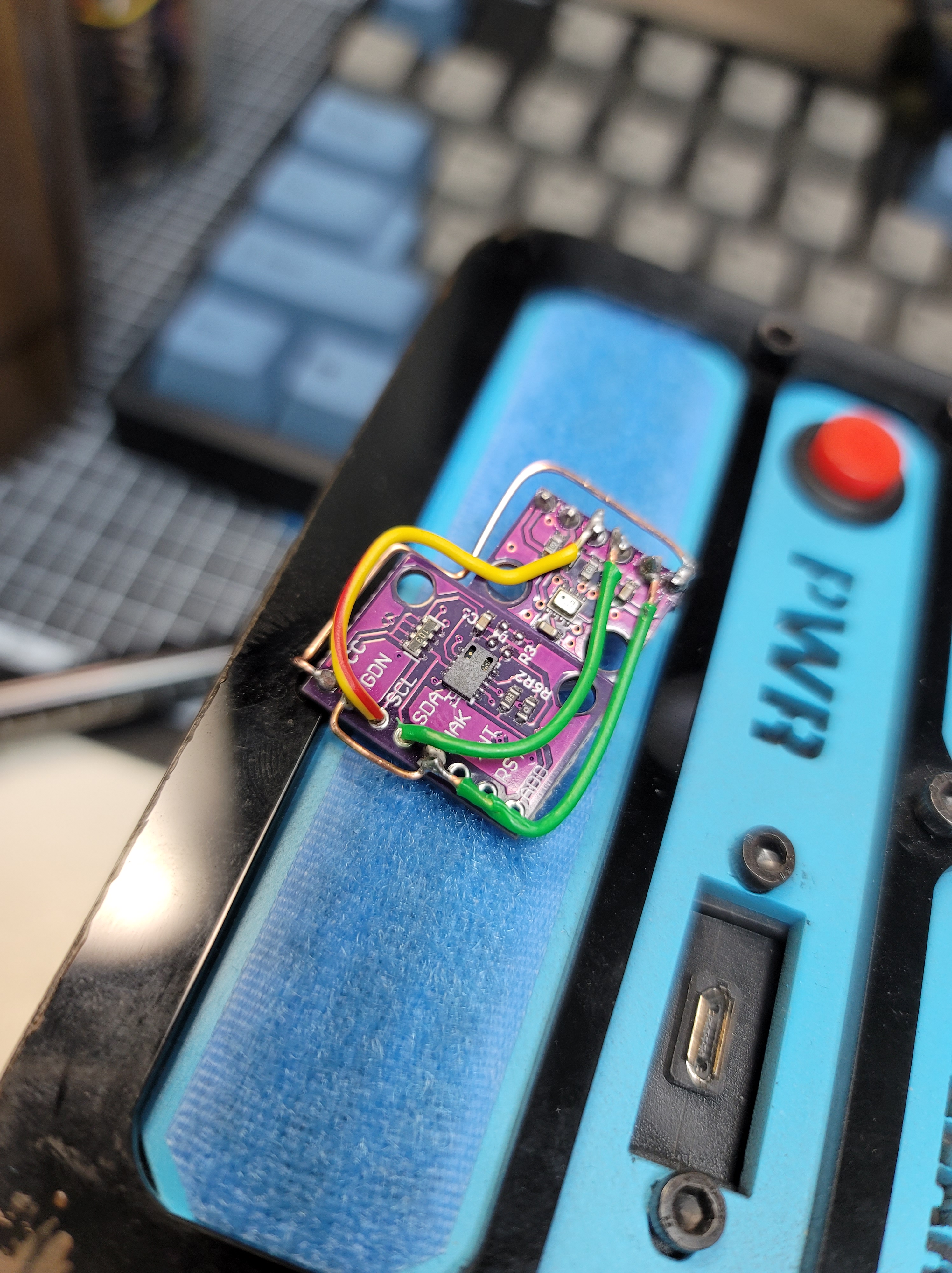
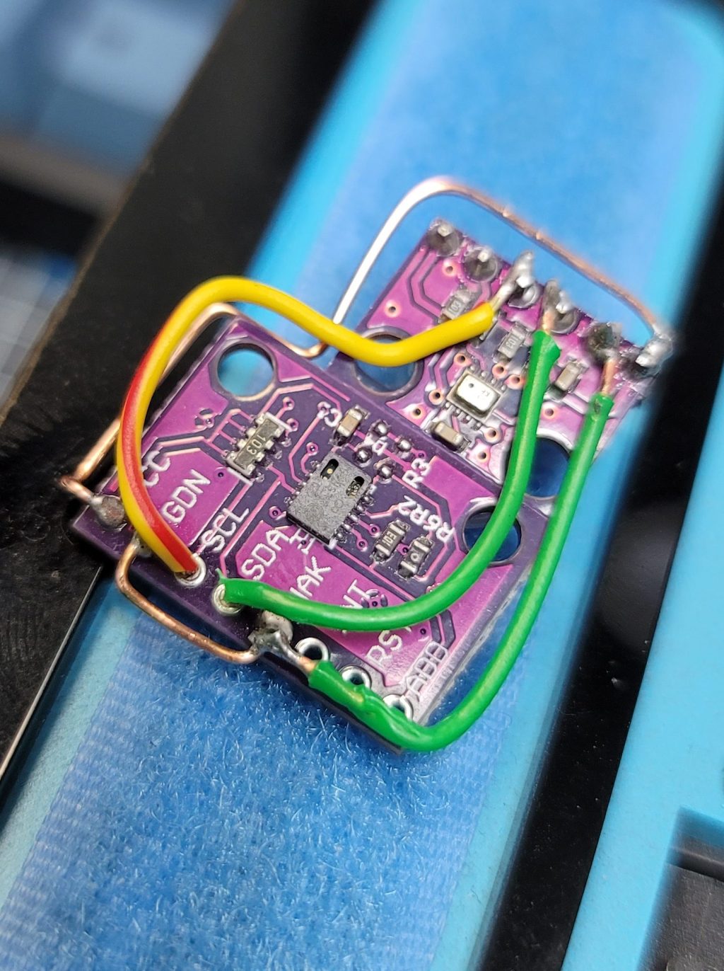
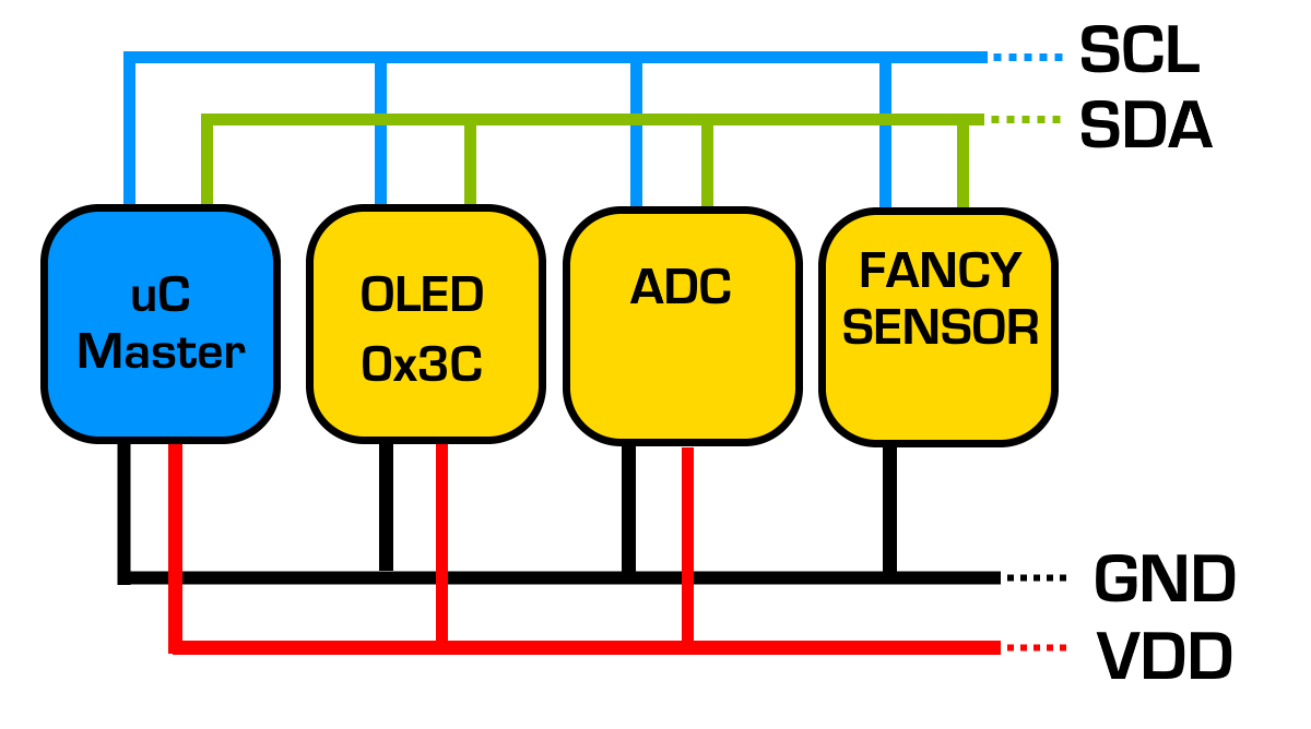
You would connect the i2c sensor or i2c display to your Arduino UNOs i2c Don’t forget to check that the VCC and GND are the right way round. Newer Arduino UNO clones have extra labelled SCL//SDA lines, but in reality, they are connected to A4 and A5. So to make it clear:
- SCL = A5
- SDA = A4

Fun fact: Working with temperature sensors? Flip GND and VCC around, and instead of a temperature sensor, you get the opposite – a heater! Amazing! (DON’T. DO. THIS)
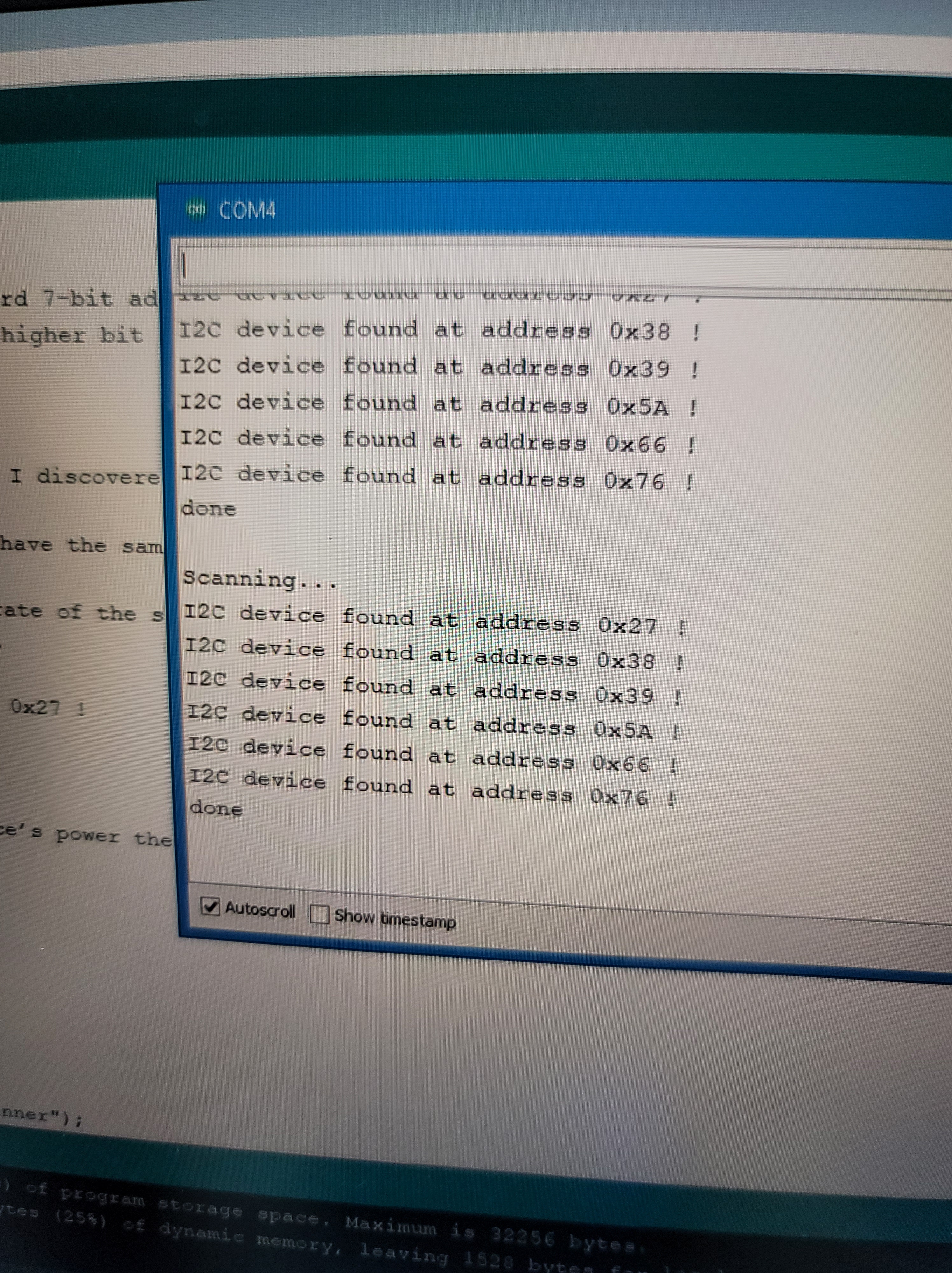
Once you’ve connected properly, and double//triple checked your connections, plug in your Arduino, upload the code, and then open your serial monitor to the right baud rate (115200) to see what devices respond!
//i2c scanner
#include <Wire.h>

void setup()
{
  Wire.begin();
  Serial.begin(115200);
}

void loop()
{
  byte error, address;
  int devices;

  Serial.println("Scanning...");

  devices = 0;
  for (address = 0; address <= 127; address++ )
  {
    // The i2c_scanner uses the return value of
    // the Write.endTransmisstion to see if
    // a device did acknowledge to the address.
    Wire.beginTransmission(address);
    error = Wire.endTransmission();

    if (error == 0)
    {
      Serial.print("I2C device found at address 0x");
      if (address < 16)
        Serial.print("0");
      Serial.println(address, HEX);

      devices++;
    }
    else if (error == 4)
    {
      Serial.print("Unknow error at address 0x");
      if (address < 16)
        Serial.print("0");
      Serial.println(address, HEX);
    }
  }
  if (devices == 0)
    Serial.println("Crikey. No I2C devices found.\n");
    Serial.println(":[\n");

  delay(8000);
}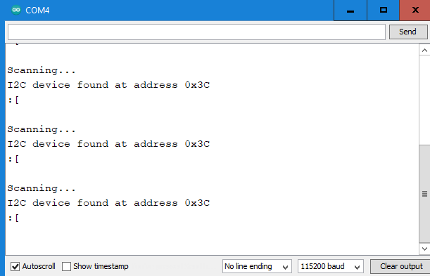
Success! We see the i2c OLED. This is useful, because the Chinese OLED clones use a different address from the Adafruit OLED modules, and so the i2c scanner can help you avoid much suffering and wasted time wondering why the device will not run.
Paul Hoets is a freelance maker who lives in South Korea. If you liked this article and would like to contribute to his empire of dirt, silicon and tech. education, buy him a coffee!